
Select keywords below to display associated demonstrations. You may alternatively use the buttons below to display all available Mechanics demonstrations or clear all selections.
Location: Cabinet 2, Shelf 4
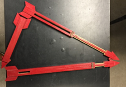
Description: This demo has two items, a straight armed and crooked arm. First, spin the straight arm making sure it is going fast enough that it is still spinning after you finish the next step. Next spin the crooked arm. While spinning the crooked arm you will have to hold down the bases. It is also important that crooked arms be spun fast enough that the bases begin to wobble once allowed to move.
Pedagogically, ask the students why the crooked arm rotor starts to wobble: if it accelerates, what is the external force that causes it to start moving? This demonstration is very useful in showing that angular momentum is not always parallel to angular velocity, unlike linear momentum and linear velocity. The rotational axis is not along a principal axis of the crooked arm rotor. To rotate about the vertical axis an external torque must be supplied (the normal force on the edge of the stand) and if that is not sufficient the system will start to wobble.


Keywords: Angular Momentum, Moment of Inertia, Heavy, Spinning, Surprise, Wobble
Location: Cabinet 2, Shelf 3
Description: The ballistic pendulum can be used to demonstrate conservation of energy. To load the canon, first remove the ball from the trap by using the release on the side facing the barrel of the canon.The release is highlighted by the green arrow in figure 2. You may need to swing the pendulum while holding the release to obtain the ball. Having the ball in hand grab the plunger. Place the ball at the face of the barrel and using the plunger push the ball into the barrel until one hears a click. Note that the canon has three possible settings. You can push the ball past the first click till you hear a second and then a third. Once the canon is loaded make sure that the protractor is set to zero degrees and is flush with the arm of the pendulum. To fire the canon, grab the yellow string and pull perpendicularly to the top of the canon until the string is taught. Once taught, continue applying pressure until the canon fires. Once the canon fires you can use the protractor to measure the maximum angle made by the pendulum arm.


Keywords: Inelastic Collisions, Intro Lab, Momentum
Location: Cabinet 1, Shelf 2
Description: This demo illustrates how the center of gravity of a body is connected to stability of the body. When performing this demo be ready to catch the balls as they do roll out of the tubes when the tubes fall. Below is a picture of what the demo looks like stored, and a picture of what should be in the box, including the instruction. It includes two plastic balls, a steel ball, a straight tube, a slanted tube, two caps, and instructions. The left image is the contents and the right is the demo stored.


Keywords: Falling, Toppling
Location: Cabinet 1, Shelf 4
Description: This demo will require a bowling ball with the hook attachment, a ladder, and the hooks on the ceiling of the lecture hall. It is advised that another person be present while setting up this demonstration. The red arrows show the hook that is attached to the ball and where they attach on the ceiling of the lecture hall. These hooks are located above the floor of the lecture hall. One will have to use the ladders located in the hallway between the demo room and the classroom to reach the anchor points.


Keywords: Bowling Ball, Classical, Pendulum, YouTube
Location: Cabinet 4, Shelf 5
Description: Shown is the working demonstration for driven harmonic oscillators.

Keywords: Driven Oscillator, Harmonic Oscillator, Resonance
Location: Cabinet 2, Shelf 1
Description: This demo has four pieces: two marbles, a stick, the base. First lift the bases and use the stick to jam the base in an elevated position as shown in the photo to the right. Note there is a small piece of felt on the lower board that marks where the stick should sit. This is highlighted with a green arrow in the right picture. Once the stick is in place, balance a marble on the nail. The nail is located at the highest point of the raised arm. The nail's location is marked by a red arrow in the right picture. Finally, in a quick motion pull the stick out of the set up and watch the marble fall into the cup.


Keywords: Complicated, Kinematics, Moment of Inertia, Rotational Kinematics
Location: Service hallway by NH 170 (Accessible by 1R button in elevator)
Description: This is a simpler version of the famous brachistochrone curve, or path of quickest descent. Four gears of equal size (stored at the end of the track) can be released simultaneously from the same height at the top of the track. There are four paths, at angles 30, 45, 60, and 75 degrees with the horizontal. It is simple to calculate the time it takes an object to slide without friction down a ramp height H and base X and traverse the final horizontal distance L-X. Minimizing the time with respect to X will prove that the optimal angle is 60.
Rather than work with sliding objects, this demonstration has gears and the tracks all have “teeth” so that the gears rotate without slipping. Instructors can make it an exercise for the students to show that this does not change the answer for the optimal angle. The difference in time for the paths is slight, so an observer is best placed at the very end of the track looking down.
Pedagogically, many students (especially more advanced ones) may expect that the time is independent of the path, since this is true for many properties of the trajectory (e.g. final velocity). It is worth having them first consider if the time of a trajectory is a conserved quantity and if not, why not.

Keywords: Calculus of Variation, Energy, Kinematics, Shortest Time
Location: Cabinet 1, Shelf 2
Description: This demo requires no setup. Simply set it onto a table, lift one of the outer balls as shown below, and let go. Next, repeat with two balls and release and two will rebound on the other side.
Pedagogically, ask the students what will happen when you release three or more balls (or four or more from the cradle with seven suspended balls). Will fewer balls on the other side leave but go higher?
Finally, you can release one ball on the left and a second ball on the right at a higher level. The subsequent motion will be a rebounding ball on the left going higher that the one on the right. Point out that is can be viewed as the “excitations” traveling through the cradle, independently.


Keywords: Click Clack, Energy Conservation, Pendulum, Surprise
Location: Cabinet 1, Shelf 2
Description: This little guy requires no setup. Make sure you have enough room on both sides for the cart to oscillate. Simply pull up the mass and let it swing. The cart will oscillate back and forth in opposition to the mass.

Keywords: Equal and Opposite
Location: Cabinet 2, Shelf 1
Description: This demo requires no setup other than ensuring that the spool is placed as shown in the images below. The spool consists of two disks connected by a cylinder of smaller radius, with the cylinder acting to spool a fabric ribbon. The spool should be placed so that the end of the ribbon comes upward from the bottom of the spool. Once in this position the ribbon can be pulled at different angles and speeds to illustrate different behaviors. It is important to ensure that there is room for the spool to roll out.
Pedagogically, the instructor can ask the students which way the spool will roll when the ribbon is pulled. The instructor can then confound every prediction in a humorous fashion. When pulled more “upward” the device will roll in a fashion to unspool the ribbon; when pulled more horizontally, the device will roll in a fashion to wind up the ribbon. Rolling without slipping implies:
Focos(θ) - Ffric = ma
-For + FfricR = Iα = Ia/R
where θ is the angle between the ribbon and the horizontal. This can be solved (assuming that there is no slipping)
a = FoR[r - Rcos(θ)]/(I + mR2)
which will change sign depending upon θ. Note that the force of friction is bounded by μN, which we assume is sufficient to cause rolling without slipping.


Keywords: Pulling, Simple, Surprise, Toilet Paper
Location: Cabinet 1, Shelf 3
Description: This demo requires no setup, only the ramp and the conical ball. Place the conical shape at the bottom of the ramp and watch it roll ‘up’ the hill. Be ready to catch the roller as there is nothing to stop it from falling off the edge of the ramp.


Keywords: Classical, Cone, Standard
Location: Cabinet 4, Shelf 2
Description: Vertically suspend a long spring from one end so that it is stretched by its own weight. When the spring is released, the top end of the spring will accelerate downwards but the bottom end of the spring will not move until the top end reaches it. This is because, locally, the forces on the bottom-most section of the spring are initially in equilibrium and remain so until the nearby portion is no longer under tension. The information that you have released the top portion can only travel at the velocity of a longitudinal wave along the spring, which is very slow. You can contrast this with releasing a vertically suspended two-meter stick. In the latter case the speed of sound in the solid wood of the stick is very high, so the compressive forces are transmitted rapidly.
This demonstration can be made more visible by attaching a brightly colored object (e.g. a yellow PostIt note) to the bottom of the spring.
This demonstration is also useful in reference to relativity about how information transfers along an object. You cannot transmit information along an object faster than the speed of sound waves along the object.


Keywords: Newton's Laws of Motion, Relativity and Information, Speed of Sound, Surprise
Location: Cabinet 2, Shelf 3
Description: There are several tops that are available in the demo room. Some have strings and others do not. If you need a string, there are spools of string in the drawer labeled ‘string’ located under the workbench on the west side of the first floor of the demo room. To work the tops, take a string that is roughly the length of your wingspan. It is better to have a shorter string than a longer one. A longer string runs the risk of getting tangled if it is not completely pulled out when launching the top. Taking care, wrap the sting around the shaft that connects to the spinning mass Once wrapped, place the top on the table. With one hand hold the top while the other quickly pulls the string. Ensure to pull through until the string comes off the top. When the string comes loose, let the top go and watch it spin. Above, is an example of stringing one of the tops available in the demo room. The left picture shows the threading of the top. The right picture shows what the top looks like after winding the string.


Keywords: Angular Momentum, Spinning, Toy
Location: Near door
Equipment Needed:
Description: Students may be confused (if they consider it at all), that it seems that by the physics definition of work, it costs no energy to hold out a weight at constant height. Pedagogically, the instructor can ask a student to hold out the weight at arm’s length and ask them if they are doing work. The goal is to get them to consider the conflict between their experience and the physics definition of work.
To resolve the matter, the same student should be asked to hold the two-meter stick with a colorful sticky-note or ribbon attached to the far end. It should be easy to see that it is not possible for the student to hold the stick motionless. That is because the muscles in their arm cannot stay contracted. In fact, the striped muscle tissue is broken into groups that work in concert, alternating between contracting and then releasing. This is because the cell membrane is “leaky,” a design that allows for fast contraction but cannot keep the cell contracted. Therefore, the student is doing lots of microscopic work when the attempt to hold the weight motionless.
In contrast, smooth muscle tissue, used in the digestive system, can stay contracted for long periods of time (thankfully). However, it is also much slower to contract and relax. Such tissue would be poorly suited for running, but well suited to keeping clenched for long times.

Keywords: Biology, Energy, Muscles, Work
Location: Cabinet 1, Shelf 1
Description: The ZipString is a battery powered toy that consists of a small, handheld motor that can drive a long loop of brightly colored string. To start the demonstration, first unwrap the loop from the device. Next, hold the motor in one hand, and with the other extend the top side of the loop out in front of you so that the string drapes in a large, untwisted vertical loop. Finally, press the button on the motor white simultaneously releasing the string from your extended hand. The loop should shoot out from the top side of the motor and be pulled in on the bottom. Keep the motor running so that the loop remains in motion.
The loop will float in the air, and moderate motions of the motor will be transferred into nearly statice shapes of the suspended loop. At the heart of this demonstration is the surprising fact that if an inelastic, ideal loop is set in motion all of the internal forces exerted by the loop will simply act to maintain the shape. (Clipped to the ZipString box is a photocopied explanation of why the loop is stable, using Newton’s equations of motion.) The external force of gravity is countered by the slight uptilt of the string as it leaves the motor.
The device has an internal battery that can be recharged with an appropriate connecting socket commonly used for small electronic devices (USB-C).

Keywords: Classical, Inelastic String, Newton's Laws of Motion, Surprise
Select keywords below to display associated demonstrations. You may alternatively use the buttons below to display all available Thermodynamics & Fluid Dynamics demonstrations or clear all selections.
Location: Cabinet 3, Shelf 2
Description: This set contains a bucket with options to make different shapes of bubble films and different solutions of film making liquids. The sphere is the surface that minimizes the surface area for a given volume; all free-floating bubbles will settle down eventually to form a sphere. Using two rings it is possible to create a film connecting the two that is shaped like a rotated catenary. Using a cube framework, it is possible to create a film on each face of the frame so that it collapses to form a “cubic bubble” in the interior of the frame.
Recipe for making long-lived bubble fluid:
Formula for giant bubbles (using bubble wand):

Keywords: Calculus of Variations, Energy Minimization, Graduate
Location: Cabinet 3, Shelf 1
Description: This demo builds off the “Pressure of the atmosphere” demonstration. The weight of the assembled spheres needs to be measured before and after the air has been evacuated from the spheres. The change in the mass of the Magdeburg sphere is very small, about 1.3g, and the sphere is around 700g. You may wish to obtain a very precise electronic scale from the machine shop. It is supposed to measure to a tenth of a gram.
Sphere diameter: ~13 cm., Sphere radius: ~6.5 cm.
Sphere volume: (4/3)πR3 = 1150 cm3 = 1.15 x 10⁻³ m
1.5g/(1.15 x 10-3 m) = 1300 g/m3 = 1.3 kg/m3
This mass can be compared to the heft of a liter bottle of water - a cubic meter of air is much more massive!


Keywords: Density, Pressure, Suction
Location: Cabinet 3, Shelf 2
Description: This demo requires no setup. To work the demo, have someone either touch or breathe warm air the sphere that has more liquid. Doing this should cause the liquid in the sphere that was touched to lower while the liquid in the other sphere should rise.

Keywords: Closed System, Pressure
Location: Cabinet 5, Shelf 2
Description: These engines work by placing a coffee mug of boiling water underneath them. The silver one is newer and works more smoothly. The fan-bladed demo is a bit harder to start, but does indeed work. If it has problems you can also place an ice cube on the top to increase the temperature difference between the top and bottom surface.
There is a large, light disk in a sealed chamber. When it is closer to the top, the air in the chamber is in good contact with the warm, lower surface. The air expands, and pushes a small piston (a bellows, in the fan-bladed demo) that then moves the disk downward. The air in the chamber is then in good contact with the cooler, upper surface and then contracts. This draws the piston (or bellows) in, which then move the large disk.
The key point is that the work is not done by the large disk in the sealed chamber acting as a pisoton. The work from the expanding/contracting air is done by moving the smaller piston (or bellows) on the side. The large disk merely shifts the air from the lower half to the upper half of the sealed chamber and back again.

Keywords: Efficiency, Heat Engines, Stirling Engine, Thermal Expansion, Work
Location: Cabinet 8, Shelf 4
Description: This device consists of a cylindrical container of small plastic beads with a rotating agitator at the bottom and a counter balanced piston at the top. As the speed of the agitator is increased the speed (“temperature”) of the beads increases, increasing the pressure. The piston rises, increasing the volume. The key idea is that the amount of momentum transferred per unit time determines the net upward force. As the volume increases, the density of beads decreases, so that there are fewer collisions per unit time, balancing out the fact that each collision transfers more momentum.
The device is normally stored with the counterweight removed from the pulleys to avoid accidentally snapping its supporting thread.

Keywords: Ideal Gas, Kinetic Theory, Pressure
Location: Cabinet 3, Shelf 1
Description: This device is a “Galton” board that shows that a set of events each acted upon with random positive and negative “kicks” or noise will result in a normal distribution of outcomes.


Keywords: Distributions, Galton Board, Statistical Mechanics
Location: Cabinet 3, Shelf 2
Description: This demo requires no set up and contains no moving pieces. All that is required is a level table. The demo may need to be filled with colored water if the overall level is getting low. When showing students, you can lift on the side of the demo to show that there is liquid inside the demo. Then students can see for themselves that the height of the liquid is the same for every container.

Keywords: Height, Pressure
Location: Cabinet 3, Shelf 1
Description: This demo requires a pump that is used to create a vacuum. It comes with a stand and two hemispheres (“Magdeburg hemispheres”). The pump connects to the nipple on the top hemisphere and then creates a vacuum inside the sphere. Once you have the pump connected and the chamber pump down you can have people try to pull the spheres apart to show the pressure the atmosphere applies to the sphere.


Keywords: Pressure, Strength, Suction
Location: Cabinet 5, Shelf 2
Description: The demo room has two steam engines available for demonstrations as shown below.
They all work under similar operations. There is a water tank which can be filled from the top as shown in the left photo below. Once the tank is filled close the tank and place solid fuel on the trough located below the tank. The trough can be pulled out as demonstrated in the right photo below. Fuel can be found in the drawer with the candles located on the west side of the demo room. Once the trough is loaded with fuel, insert back under the tank and light the fuel. Once the fuel is lit ensure that the valve on the tank is closed and the valve leading to the generator is open. Then monitor the water using the side window. When the water is boiling give the generator a push and the steam should take over.


Keywords: Chambers, Piston, Pressure
Location: Cabinet 5, Shelf 1
Description: There are three packet handwarmers each containing a supersaturated solution of sodium acetate and a small concave metal disk. When pressure is applied to the disk causing it to “click”, the pressure shock will trigger the precipitation of the sodium acetate, forming a rapidly propagating crystallization front and liberating a substantial amount of heat.
This is an example of a first order phase transition, with the heat released equaling the latent heat associated with the entropy change from liquid to crystal.
When the samples are returned, they must be immersed in a container of boiling water until the crystals go back into solution. It may help to mechanically compress the packet, breaking up crystals into smaller ones that dissolve more quickly. Once there are no crystals in the packet, the water and packets should be allowed to cool slowly, creating the supersaturated state.

Keywords: First Order Phase Transitions, Latent Heat, Phase Transitions, Supersaturated Solutions
Select keywords below to display associated demonstrations. You may alternatively use the buttons below to display all available Waves demonstrations or clear all selections.
Location: Cabinet 4, Shelf 5
Description: These blocks are used to illustrate the relationship between pitch and length. One simply sets the block on the table, and then using the rubber mallet gently strikes the tops of the boxes. The boxes will produce different tones. Note that some of the boxes are cracked and should be handled with care until we have replacements.


Keywords: Music, Sound, Tones
Location: Cabinet 4, Shelf 4
Description: These shells can be blown into to produce a loud, rich tone. They take some practice to work smoothly, and are loud. You play them in a similar manner as a trumpet. Make the ‘M’ sound as you place the opening shown in the picture to your lips. Then while keeping your lips pressed together, blow. Without the shell, the shape of your mouth as you blow should sound like an elephant.

Keywords: Music, Resonance, Sound
Location: Cabinet 4, Shelf 4
Description: This is a wooden xylophone. It can be held up by one hand and stuck with the other if there is no place to hang it. The rubber mallet seen in the photo is what one uses to strike the instrument, and this mallet can be used with tuning forks.

Keywords: Music, Resonance, Sound, Wavelength
Location: Cabinet 4, Shelf 5
Description: These demos will require the boxes shown below and some sort of compressed air.
Both boxes have a nipple where one can connect a hose to blow air into the box. Once air is flowing you can change the pitch of the box by sliding the top in and out. Both boxes should have markings indicating the note at each length.


Keywords: Music, Sound
Location: Cabinet 7, Shelves 4 and 2
Description: Spectrum tubes use a high voltage power supply. It is important to use a power supply that will protect you from electric shock. A safe power supply has specially molded spring-loaded sockets to hold the tube, and heavy casing. The power supply switch should always be in the off position when removing or placing the tubes in the power supply.
Spectrum tubes are filled with a low pressure gas or vapor of an element or molecule. A spectrum tube should only be powered for 30 seconds at a time, and then allowed to rest for 30 seconds before powering it again.
The department has a large number of small cardboard tubes that each have a diffraction grating at one end. These can be used to view the various sources when the source is energized.
With that in mind, it's a good idea to get students to practice viewing the spectrum of fluorescent lights in the classroom before viewing the demonstration tubes. That way they can orient the diffraction grating and get used to what they should look for when viewing a spectrum.

The below is an older set of spectrum sources that need to be hooked up to a high voltage supply. It is bulkier and harder to use.

Keywords: Astronomy, Astrophysics, Diffraction, Spectra
Location: Cabinet 4, Shelf 2
Description: After making sure the metal plates are suspended via the strings on either side of each box, strike the metal to produce a tuning fork sound that is the same in each box. They can be moved around the room to demonstrate sound properties while continually holding a tone. However they should be placed before being striked as any movement quickly dampens the sound.

Keywords: Hanging Metal, Single Toned, Sound, Tuning Fork
Location: Cabinet 4, Shelf 4
Description: These are forks that can be struck with a rubber mallet to produce a tone. You can also strike them on the palm of your hand. It is not advised to use a hammer, table, or any hard surface to strike tuning forks. The forks should be marked with what frequency they produce.

Keywords: Sound, Tones, Tuning Fork
Select keywords below to display associated demonstrations. You may alternatively use the buttons below to display all available Electromagnetism demonstrations or clear all selections.
Location: Must be assembled: horseshoe magnet is on lower level on magnet rack; wires hang below magnet rack, ringstands on lower level with clamp hardware; current supply is in DC voltage source cabinet on lower level.
Description: The “Force between current carrying wires” demonstration can be a bit subtle because the fields and therefore the force generated are small, leading to a small deflection of the wires. This demonstration uses a strong horseshoe magnet and some clever rigging to maximize the deflection of a single wire carrying a large current. The magnet is quite heavy, and needs a bit of support to stay in the correct orientation.
Using the current source shown, even at its lowest setting, produces a deflection of over 8cm. Turning it on can generate a substantial kick which should be visible even in the large lecture hall.


Keywords: Force on Moving Charges, Lorentz Force
Location: TBD
Description: A high voltage transformer and two copper rods that can be inserted into sockets and fastened in place.
Arrange the copper rods so that there is a small air gap between them at the base. The very large voltage will ionize the air between the two electrodes, creating a conducting path, allowing current to flow. The air will be heated by the current and rise, until the length of the electric arc is so long that the voltage is insufficient to maintain ionization. This process will repeat.
The arc is hot enough to set paper on fire if it is inserted between the electrodes.
Dielectric breakdown at electrical substation video: https://www.youtube.com/watch?v=PXiOQCRiSp0

Keywords: Dielectric Breakdown, Lightning, Voltage
Location: In front of Cabinet 4 in box on the floor
Description: There are several pipes in the demo room that can be used with/instead of the copper pipe shown. Taking a spherical magnet, drop it down a metal pipe, and the changing magnetic flux through each horizontal slice of the pipe will induce a current that in turn generates a magnetic field that opposes the change in flux. This will slow the magnet’s fall. For the purpose of showmanship, an unmagnetized ball bearing is also available which you can use to switch out with the magnetized one to make it seem that when the student drops the ball bearing it moves slowly, but when the instructor drops it, it moves normally.
There are two copper pipes of differing thickness as well as an aluminum one and a plastic one. Since the changing magnetic field induces a voltage, the dissipation (V2/R) is largest when the resistance is smallest. There is no current generated with the plastic pipe so the magnet will fall normally. Teachable moment: a “perfect conductor” will generate an opposing field causing the dropped magnet to levitate in place.
Caution: The magnets are strong, and if not handled with care, can easily be shattered when they are collide rapidly with a ferromagnetic material.

Keywords: Induced Currents, Lenz's Law, Magnetic Damping, Magnetic Levitation
Location: Cabinet 6, Shelf 2
Description: A carefully balanced lever has a closed metallic loop on one end and a metallic “C” forming a similar shape but not closed on the other. The metal is non-magnetic. When a strong magnet is moved near the closed loop, it will oppose the change in magnetic flux, moving away from a magnet that approaches the loops and towards a magnet that is pulled away from the loop. This occurs because the induced current in the closed loop produces a magnetic field that opposes the change in flux.
Ideally there is no effect on the “C” end of the balance because there is not a closed loop. However, an extremely strong magnet will still produce a weaker effect. To see why, treat the gap in the “C” as if it were closed by a capacitor. For large changes in flux there will still be a current induced, with a displacement current across the gap.
Be sure to demonstrate that the balance itself is completely non-magnetic!

Keywords: Induced Magnetism, Lenz's Law, Magnetic Induction
Location: Cabinet 6, Shelf 2
Description: This demo requires no setup. It is just three magnets that ‘levitate’.

Keywords: Magnet, Repulsion
Location: Cabinet 6, Shelf 3
Description: This demo requires no setup. Check to ensure the bulb filament is not burned out and turn the handle. This will cause the bulb to light up.


Keywords: Crank, Filament, Fluorescent Lightbulb, Manual
Location: Cabinet 2, Shelf 2
Description: This demo comes as a kit of pendular blades, a pair of magnets in a C-shaped jig, and a black supporting rod with a pre-cut slot in it from which to suspend a blade such that it will swing between the poles of the magnets. The ring stand is in the lower level of the demo room with all of the stands and clamps.
When the solid blade swings between the poles of the magnets, it comes to an abrupt halt. Its motion induces a large eddy current that opposes the change in flux through the conductor and also dissipates the kinetic energy of the moving blade. However, when the comb-shaped blade swings between the poles, the geometry of the blade does not allow large current carrying loops, and the motion is not damped. Finally, when the slotted blade (the blade with long slotted holes) swings between the poles of the magnets its motion is damped. The continuous conducting path along the top and bottom of the slots allows for a large loop of current to be induced, again stopping the blade.


Keywords: Guillotine, Induced Currents, Lenz’s Law, Magnetic Damping, Magnetism
Location: TBD
Description: This apparatus demonstrates the force between two parallel current-carrying wires.
Warning: Because the currents required to produce a noticeable force between two wires, the power supply is specific for this demonstration and should not be used for other applications. Evidence for the size of the currents involved is found in the melting of the plastic sheet separating the wires when the wires were drawn towards each other by their magnetic interaction. There is a knife switch on the top of the demonstration box that allows the currents to be switched between parallel and anti-parallel. The deflection of the wires is small, and so this demonstration is more suited for classes where students can move in close for an observation.
By flipping the switch repeatedly, it is possible to push the wires in resonance with their natural oscillation frequency in order to get a larger amplitude displacement.


Keywords: Bio-Savart, Current, Magnetic Force, Magnetism
Location: Cabinet 6, Shelf 4
Description: These are two pasco electrical boards. They come with manuals on how to use them and ideas for labs/demos.

Keywords: Circuit, Electrical, PASCO
Location: Cabinet 5, Shelf 4
Description: Thread the long conducting cylinder through the solid ring (upper ring, in figure shown) and let the ring rest on the disk above the base. When the power is switched on, a large AC current will flow through the coil, creating a large magnetic field collimated by the permeable core. This changing flux induces a current in the ring. The current in the ring will itself create a magnetic field that opposes the changing magnetic flux, causing the ring to launch very rapidly into the air.
A second ring, which has a split in it, (lower ring in figure) is also provided. This slit or gap in the ring prevents current from flowing around the ring and so no opposing magnetic field will be generated. This second ring will not launch into the air, even though the gap is quite small.


Keywords: Electromagnetic Induction, Lenz's Law, Magnetic Repulsion
Location: Main generator is in the cabinet under the upper level platform, rear of area. Additional generator in location TBD.
Description: A rubber belt is driven between a set of electrified contacts (bottom) and a metal globe. The belt mechanically pushes the charges against the electric potential and deposits them on a contact in the field free region inside the globe. This allows a substantial voltage to be developed between the sphere and ground. A grounded metal wand is attached to the unit allowing the voltage to be discharged. The dielectric breakdown field of air is ~3MV/m, so if a spark jumps from the globe to the wand when they are separated by ~ 10cm, the potential difference must be on the order of 100,000V. However, the total current in a spark is tiny.
Possible demonstrations include:
Charging by conduction and induction.
Levitating pie tins (charged by conduction, then the electrostatic force causes them to fly off).
Flying styrofoam (packing peanuts).
Ionic propulsion (A rotor with sharp endpoints will ionize the air near the tips of the rotor, and by repelling them cause the rotor to spin).
Fly-away hair (subject must have long hair. There is an insulated stand available in the cabinet. After demonstration, if the generator is turned off and the subject removes their hand from the generator, they will slowly discharge to the air without generating any (mildly) painful shock.

Keywords: Dielectric Breakdown, Electric Fields, Electrostatics, Voltage
Location: Cabinet 5, Shelf 4
Description: A Wimshurst machine or generator uses the principle of electrostatic induction to generate a large charge imbalance and thus a voltage. It does not rely upon friction to create a separation of charge. Instead, it uses the initial, random, thermodynamic fluctuation of charge to initially charge one side of the system (say, positive). By clever connections of conductors this microscopic imbalance is used to induce a charge to transfer to the other side (in this case, negative). That induced charge then acts back on the original conductor to pull more positive charge onto its plates. After a few cranks a sufficient voltage is built up to cause a spark to jump from one of the spherical electrode to the other, if the gap is small. (See Wikipedia for a clever animation of this process.)
A second important feature are the cylindrical capacitors on each side, similar to Leyden jars. If they are connected to the generator (simply by flipping each of the conducting rods to make contact between the generator and the cylinders then charge can flow from the generator to the capacitors). Given the relationship for capacitors:
Q = CV
If the breakdown voltage for the air gap between the spherical electrodes is unchanged, a larger capacitance (C) allows a larger charge (Q) to be stored on the capacitors before the spark jumps. Operationally, this means that it will take many more turns of the generator handle before a much larger and louder spark jumps between the electrodes.
The demonstration works better in dry air, and thus works better late in the Fall semester and early in the Spring semester. When the capacitors are not connected and the spherical electrodes have a small separation, then at a moderate rate of cranking a soft “click-click-click” can be heard about once a second. The associated spark is dim. When the capacitors are connected, it can take twenty seconds or more to charge up to a sufficient voltage to generate a much louder and brighter spark.
The breakdown field for dry air is approximately 3 kV/mm (kilovolts per millimeter) or 3.0 x 10^6 V/m (volts per meter), so if the gap between the electrodes is N centimeters, the voltage at breakdown is N x 30 kV.
See also: Kelvin Water Drop Generator

Keywords: Capacitance, Electric Charge, Charge Generator, Electrostatic Induction, Generator
Select keywords below to display associated demonstrations. You may alternatively use the buttons below to display all available Quantum Mechanics demonstrations or clear all selections.
Location: Cabinet 7, Shelf 2
Description: This demo will require liquid nitrogen or some other method of cooling down the blocks. Below are the different parts of the demo. You can see the blocks in the top right corner of the box in the right picture.
When storing the demo make sure the black blocks are dried, and stored back with the gel packs. Leaving them wet will damage them.
NOTE: This demo is heavy. Please be careful carrying it down and up the stairs.


Keywords: Liquid Nitrogen, Magnet
Select keywords below to display associated demonstrations. You may alternatively use the buttons below to display all available Tools & Resources or clear all selections.
Location: Cabinet 1, Shelves 3 and 4 with larger balls on the bottom shelf
Description: A collection of different sizes and types of balls for use in various demonstrations.
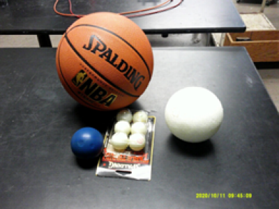
Keywords: Collisions, Energy Conservation, Momentum, Rolling
Location: Cabinet 3, Shelf 1
Description: The demo room has an assortment of glassware. Most of this glassware is not tied to a specific demo, but can be used as needed.
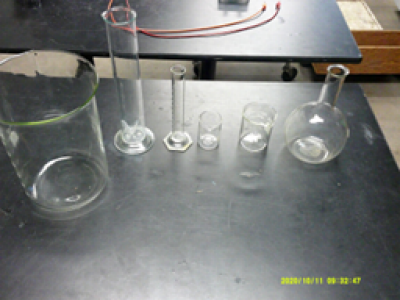
Keywords: Liquid, Measure
Location: Under stairs, back of lower floor of demo room.
Description: When assembled, this frame has a volume of one cubic metter. This is useful for discussions of the metric system, density and air pressure. There are a million cubic centimeters in a cubic meter.
This is useful for the measurement of the density of air demonstration. One cubic meter of air at atmospheric pressure has a mass of about 1.3kg.
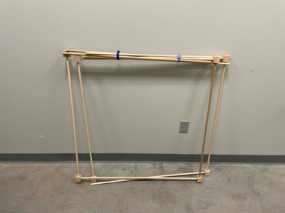
Keywords: Air, Density, Measure, Metric System, Thermodynamics
Location: Cabinet 5, Shelf 4
Description: Some glass dewars and insulated containers for transporting liquid nitrogen (LN2). If the departmental LN2 tank is not currently providing LN2, it can be procured from the Chemistry Stockroom. The latter will only provide it if it will be transported in the back of a pick-up truck or similarly vented vehicle. Check with the Machine Shop to see if someone can pick it up for you.
Keywords: Boiling, Liquid Nitrogen, Phase Transitions, Temperature, Thermodynamics
Location: Cabinet 7, Shelf 3
Description: The official name for this is a “Hoberman sphere, named after the inventor. It is a demonstration of how in an expanding universe every point runs away from every other point. The blue-green hinges glow in the dark, if they have been exposed to a strong light.
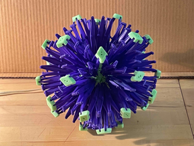
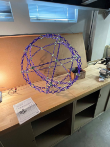
Keywords: Astronomy, Astrophysics, Cosmology
Location: Cabinet 6, Shelf 5
Description: Various types from incandescent to UV
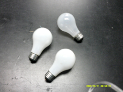
Keywords: Electricity, Light
Location: Cabinet 1, Shelf 1
Description: There are also balances on shelf 1 and hanging scales on shelf 2.
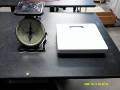

Keywords: Measure
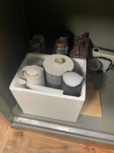
Location: Under stairs, back of lower floor of demo room.
Description: This electrically powered, portable vacuum pump can be used for a variety of demonstrations such as the role of air resistance in the motion of falling objects, finding the density of air, demonstrating the large value of atmospheric pressure, or how sound depends upon air for propagation. The box around the pump is held in place with a “T” shaped pin that is released by depressing the button in the center of the pin. When the box is secured in place, the pump can be pulled along by a wire strap with a handle.
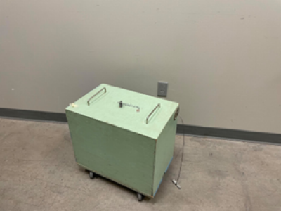
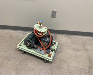
Keywords: Air, Pressure, Thermodynamics, Vacuum
Location: Cabinet 2, Shelf 1
Description: These arrows are supposed to show how we add and subtract vectors. There are three arrows. Two arrows that can change size and one that is fixed. Below is illustrated the arrows and how they change size.
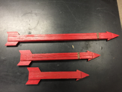
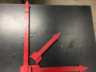
Keywords: Arrow, Vectors
