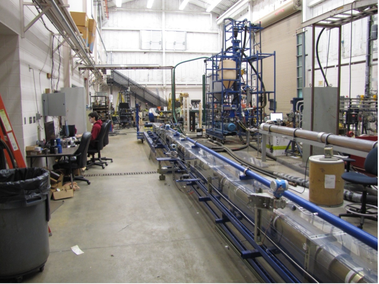
The hole-cleaning investigation flow loop is a state-of-the-art facility that has been developed to study wellbore cleanouts during drilling and completion operations. The loop enables investigations with varying wellbore inclination, mud circulation rate, and temperature. The main components of the setup include: i) annular (5” x 2.4”) and 2-inch pipe sections; ii) a fluid preparation and circulation tank; iii) a solids injection tank; iv) a solids collection tank; v) circulation pump with a circulation capacity of 400 gallons per minute; vi) two hydrocyclones for separating solids from the return fluid; vii) a heating system for elevated temperature experiments; viii) measuring instrumentation consisting of two Coriolis flowmeters, two differential pressure transducers, and transmitters for measuring pressure, pipe speed, and temperature; and ix) a Data Acquisition (DAQ) system for displaying and recording experimental parameters. The annular test section is fully transparent to visualize cleanout mechanisms and measure bed height.
WCTC Equipment
Flow Loops
Hole-Cleaning Flow Loop
High-Velocity Multiphase Flow Loop
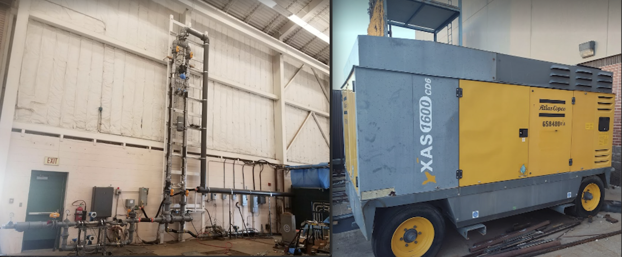
The multiphase flow loop at the Well Construction Technology Center (WCTC) is a cutting-edge research facility designed to conduct precise experiments under extreme velocities, achieving critical or sonic conditions where upstream pressure becomes decoupled from downstream pressure. The flow loop comprises pipe and annular test sections arranged in a parallel configuration to facilitate multiphase experiments in a vertical orientation. The facility is equipped with auxiliary systems, including a water circulation system, an air injection system with compressors, Coriolis flow meters for measuring gas and liquid flow rates, a high-speed video camera system, quick-closing and modulating control valves for flow adjustments, and comprehensive measurement and instrumentation systems. The internal diameter of the test sections is 83 mm, with a 35 mm outer diameter pipe installed in the annulus. The concentricity of the pipe is maintained by 3 mm screws laterally mounted at the entrance and exit sections. Measuring instruments installed on the test sections include differential pressure transmitters, static pressure transducers, and temperature transmitters, which monitor pressure and temperature variations during the experiments. The experimental setup enables the determination of liquid holdup based on liquid level measurements. Additionally, transparent polycarbonate viewing ports on the test sections allow for the detection of flow regimes by recording video clips during the experiments.
High-Temperature Flow Loop

The high-temperature flow loop at the Well Construction Technology Center (WCTC) has been developed to investigate novel lost circulation materials for geothermal applications under high-temperature conditions. Specifically, the loop is designed to study the impact of shape memory polymer (SMP) on fluid rheology, wellbore hydraulics, and SMP sedimentation behavior. Two primary test sections are included in the flow loop: i) a 10-foot horizontal pipe viscometer for examining the flow behavior of test fluids and wellbore hydraulics, and ii) a ten-foot concentric annulus with two viewports and an inner pipe rotation motor for testing the flow behavior of test fluids and wellbore hydraulics. Visualizing the annular flow of fluids containing SMP through the viewports is possible. A heating system is integrated into the setup to elevate the test fluids to the desired temperature. During heat transfer, oil is circulated through electric heaters and then to a coil inside the fluid circulation tank, where it is cooled before being returned to the oil tank.
Downhole Separation Flow Loop

The downhole separation flow loop at the Well Construction Technology Center (WCTC) was constructed in 2019 with support from Echometer Company. This facility has been developed to investigate the efficiency of downhole separators when applied before artificial lift pumps. Various types of gravitational and centrifugal separators have been tested using this facility. The facility simulates both casing and tubing sections of a producing well. Liquid and gas flow rates are measured at the inlet, tubing outlet, and casing outlet. These flow measurements provide an accurate estimation of the separator’s performance in sending the liquid into the tubing and the gas into the casing. In addition, the facility is equipped with all the required valves, pressure sensors, and temperature sensors. Air flow rates up to 1600 cfm and water flow rates up to 23 gpm can be tested, at pressures up to 60 psig. Upon modification, the facility can handle higher pressures or rates. Having the casing and tubing sections and all the required sensors makes this facility an ideal choice for various artificial lift and production engineering projects.
Fracture Flow Setup
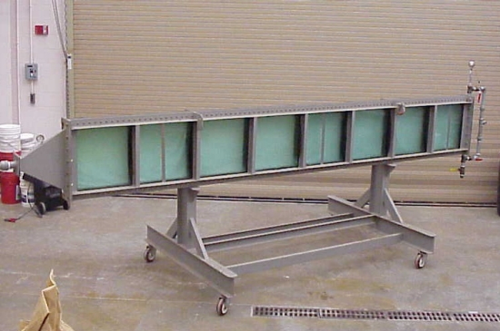
The fracture slot setup is designed to facilitate the visual analysis of slurry flow and proppant distribution within a simulated fracture. This setup consists of a 25-foot-long slot section created by a framework that encapsulates two glass slabs, each with a thickness of 0.75 inches, with a 0.5-inch slot section between them. This configuration allows for a clear view of the flow pattern and structure during testing. To conduct tests, a high-speed camera is employed to capture detailed visualizations of the slurry flow within the fracture. This setup enables researchers to closely observe and analyze the behavior and distribution of proppant as it is placed within the fracture. During testing, the fracture slot is connected to a flow loop system for preparing the test fluid and circulating it through the slot section at the desired flow rate. The flow loop ensures that the test conditions are consistent and controlled, allowing for accurate and reproducible results. This setup is instrumental in studying the dynamics of slurry flow and proppant placement in a fracture, providing valuable insights for optimizing hydraulic fracturing processes.
Tubing Multiphase Flow Loop

The tubing multiphase flow loop at the Well Construction Technology Center (WCTC) has been developed to investigate liquid-gas flow in vertical tubulars. The facility is equipped with the required temperature, pressure, and differential pressure sensors. In addition, a pair of quick-closing valves are used to measure the liquid holdup in the tubing. High-definition cameras are used to record and analyze the liquid-gas flow pattern for each test. A wide range of liquid and gas flow rates can be tested, with a maximum air flow rate of 1600 cfm and a maximum water flow rate of 23 gpm. The facility has been used to analyze liquid loading in gas wells and the effects of partial tubing restrictions on the flow dynamics. It is currently used to simulate the water-steam flow in high-temperature geothermal wells. The collected data will help in development of a virtual flow meter for such wells.
HPHT Foam Flow Loop

This experimental setup has been developed to generate stable foam under high-pressure (maximum 5000 psi) and high-temperature (maximum 350°F) conditions and perform rheology and hydraulics tests using different diameter pipe and annular test sections. In addition to performing these experiments, the system generates foam and circulates through a stability cell to measure foam drainage under pressurized conditions. High-pressure nitrogen gas, supplied at 6000 psi, will pressurize the loop. Test temperature is controlled using a chiller and electric heater that provides the cooling or heating media. The cooling or heating fluid passes through double-pipe heat exchangers that are installed in the flow line to cool or heat the foam circulating in the loop. The flow loop is fully insulated to prevent heat loss or gain. A needle valve induces shearing and uses pressure energy for foam generation and static mixers are installed upstream and downstream of the valve to maintain homogeneity of the foam. A Coriolis flow meter measures the density, flow rate, and temperature of test fluid during the test. A data acquisition board that is linked to a VBA program and spreadsheet is used for monitoring and recording test parameters.
Medium Pressure Foam Flow Loop

This experimental setup comprises ½”, ¼”, and 3/8” straight tubing sections, along with a ½” coiled tubing section. Initially designed to investigate foam flow within these sections, the setup has since been utilized to study various other fluids. Insulation is applied to nearly all parts of the setup. A Coriolis flow meter facilitates multi-variable measurements, including mass flow rate, volumetric flow rate, density, and temperature. Flow control is achieved manually via the variable speed transmission of a positive displacement progressive cavity pump. The pump is supplemented by a centrifugal pump serving as a suction booster. The rupture disk of the pressure relief valve for the pump is set at 850 psig. Experiments can be conducted at a pressure of up to 800 psi and a temperature of 180°F. The test fluid is heated using a copper coil placed in the fluid circulation tank.
Coiled-Tubing Setup
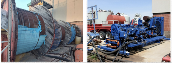
This setup is designed for conducting hydraulic experiments to study flow dynamics in coiled tubes and the impact of friction reducers. It features three coiled tubes and straight sections with diameters ranging from 1 inch to 2 inches. Additionally, it includes dedicated storage and a circulation system. A Halliburton mixing truck, equipped with two 50-barrel tanks, prepares a slurry of sand and frac gel. Two triplex mud pumps circulate the slurries through the coiled tubes and straight sections, with a centrifugal pump serving as a suction booster for the triplex pumps.
Cement Aging Setup
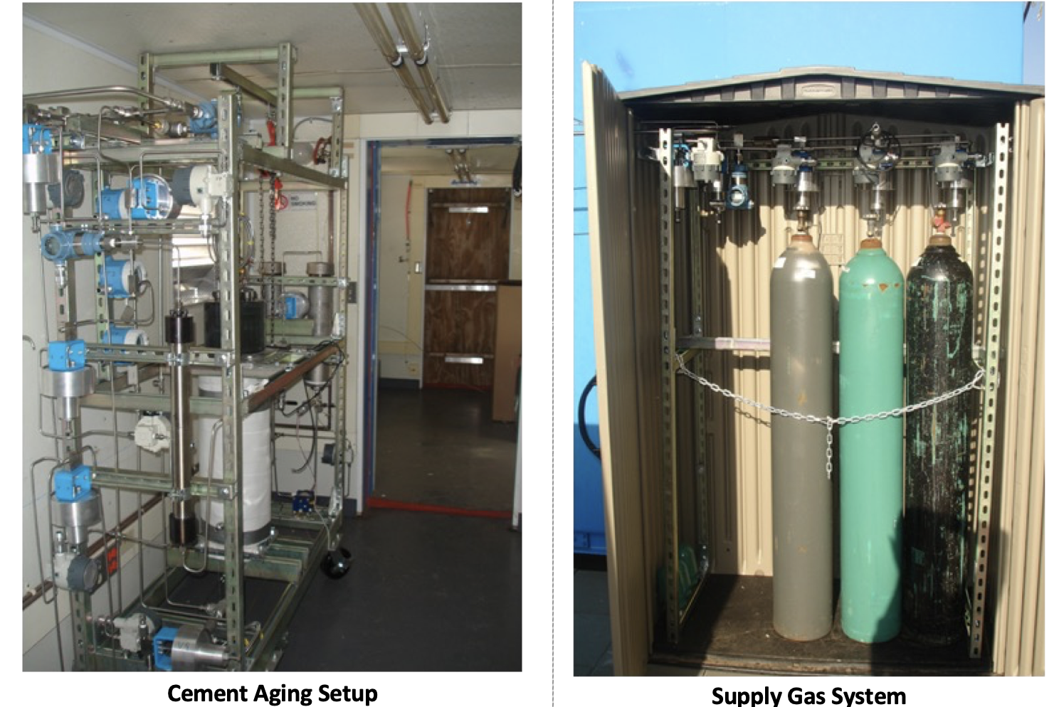
The setup is developed to investigate the degradation of cement under high-pressure high-temperature (500°F and 10,000 psi) borehole conditions. Cement samples can be aged in brine solutions in the presence of acidic gases such as carbon dioxide and hydrogen sulfide. The setup consists of:
I. An aging cell with a 3-liter volume capacity;
II. Three gas cylinders filled with test gases (CO2, methane, and methane mixed with H2S);
III. A gas injection cylinder (250 ml capacity) to accurately control the composition of the gas phase in the aging cell;
IV. Measuring instruments and a data acquisition (DAQ) system.
The injection cylinder is equipped with a floating piston that separates the cylinder into two chambers. The lower chamber is used to meter and inject the gases needed for the aging process, while the upper chamber is connected to an oil pump and reservoir. The oil pump fills the upper chamber, moving the piston downward to pressurize and inject the gas phase into the aging cell. The hydraulic oil flows back to the reservoir when the lower chamber is refilled with gas from one of the test gas cylinders. The piston's location is determined by the liquid level measured in the oil tank.
During the aging test, cement cores and shear bond samples can be placed in the cells using a specially designed shelf (a round multilayer rack). The cell is filled with brine until all samples and cores are completely immersed. Then, the lid is placed on the cell, and the gas inlet line is connected. Gas injection begins by opening the valve between the injection cylinder and the aging cell. Gas is injected into the cell repeatedly until the cell pressure reaches the desired value.
Corrosion Testing Facility
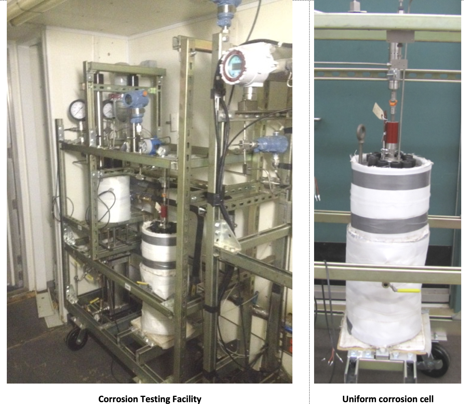
The corrosion testing facility comprises three experimental setups designed to study: i) stress cracking corrosion, ii) uniform corrosion under static and dynamic conditions, and iii) hydrogen embrittlement. The facility includes four corrosion and hydrogen embrittlement test cells, two gas accumulators, a gas injection cylinder, a pneumatic power cylinder with a regulator, and a magnetic drive system with an air motor. The setups are capable of operating under high-pressure, high-temperature (HPHT) sour gas environments. They are connected to auxiliary systems such as heating, gas supply, and injection systems. A data acquisition (DAQ) system displays and records all experimental parameters, with critical test parameters automatically controlled by the DAQ system. These experimental setups accurately simulate field conditions by varying pressure, temperature, and aging/test fluid composition. The autoclave and other equipment handling test fluid are placed in a separate room where only intrinsically safe equipment and instruments are used.
Stress Cracking Corrosion Setup
In this test setup, mini-pipe specimens are used for stress-cracking corrosion experiments. One end of the mini-pipe is plugged, and during the experiment, both ends are attached to a pulling rod installed at the bottom of the corrosion cell. This rod is connected to a power cylinder to apply the force needed to generate the desired stress level in the specimen. A double-acting pneumatic cylinder is used to provide this force, applying a pull force to maintain the specimen under constant tensile stress. Nitrogen from a supply cylinder is used as the pneumatic fluid to actuate the cylinder. During the test, the internal and external sides of the mini-pipe specimen are pressurized and maintained at different pressure levels. This setup simulates underbalanced and overbalanced wellbore conditions, helping to reliably detect the stress cracking point as pressure begins to communicate between the interior and exterior parts of the specimen. Both sides of the specimen are exposed to a test solution saturated with sour gases. To ensure sufficient dissolution of surrounding gas, two gas accumulators with a volume capacity of 250 ml are directly connected to the inside and outside of the specimen. These accumulators are filled with test gas using the injection cylinder.
Uniform Corrosion Setup
This facility allows the use of flat coupons to conduct uniform corrosion tests under static and dynamic conditions. The coupons are covered with a protective coating except for the exposure area (one side of the gauge zone). Three specimens are mounted inside a sleeve using a high-temperature silicone seal. After setting, the sleeve with the coupons is inserted into the autoclave, and a cylindrical rotor is placed in the middle of the sleeve. The autoclave is filled with a test solution that is deoxygenated by purging the cell with pure nitrogen. The test cell is then heated to the desired temperature and pressurized by injecting test gases to the required pressure. The corrosion test typically lasts for 168 hours (7 days).
Hydrogen Embrittlement Investigation Setup

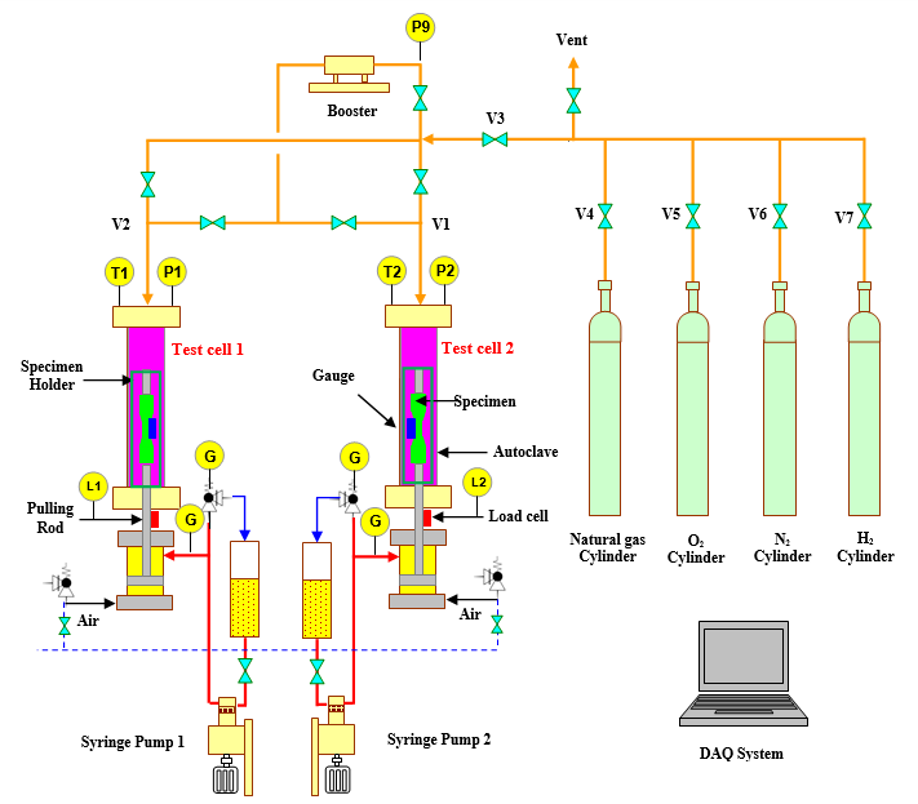
This experimental setup is developed to perform hydrogen embrittlement (HE) studies on different pipeline materials. Two newly constructed autoclaves (test cells) with a capacity of 3.1 L are installed in the setup for testing in-situ hydrogen embrittlement in pipeline steel. The cells are large enough to accommodate various specimen designs, holders, and clip-gauge assemblies. The cells are jacketed to allow heating and cooling by circulating heat transfer fluid (glycol) during the experiment. Custom-made aluminum jackets are designed and manufactured to cover the autoclave body. A high-capacity chiller and a 6-KW electric heater control the glycol temperature.
As the specimen is stretched during the test, an axial force is applied to a pulling rod using a hydraulic cylinder mounted underneath the autoclave. There is a seal gland on the bottom side of the autoclave for the rod. It connects directly the specimen to a load cell, which is connected to the hydraulic cylinder through a universal joint. A programmable syringe pump controls hydraulic pressure during the experiment. An oxygen sensor is installed on the outlet line of the autoclaves to monitor exit-gas oxygen content and confirm proper purging of the air from the system. Various sensors are installed in the setup to measure and monitor critical test parameters such as temperature and pressure. In addition, lower explosive limit (LEL) sensors are mounted on the setup to detect hydrogen and natural gas leaks.
Hydrogen Embrittlement Investigation Setup
This experimental setup is developed to perform hydrogen embrittlement (HE) studies on different pipeline materials. Two newly constructed autoclaves (test cells) with a capacity of 3.1 L are installed in the setup for testing in-situ hydrogen embrittlement in pipeline steel. The cells are large enough to accommodate various specimen designs, holders, and clip-gauge assemblies. The cells are jacketed to allow heating and cooling by circulating heat transfer fluid (glycol) during the experiment. Custom-made aluminum jackets are designed and manufactured to cover the autoclave body. A high-capacity chiller and a 6-KW electric heater control the glycol temperature.
As the specimen is stretched during the test, an axial force is applied to a pulling rod using a hydraulic cylinder mounted underneath the autoclave. There is a seal gland on the bottom side of the autoclave for the rod. It connects directly the specimen to a load cell, which is connected to the hydraulic cylinder through a universal joint. A programmable syringe pump controls hydraulic pressure during the experiment. An oxygen sensor is installed on the outlet line of the autoclaves to monitor exit-gas oxygen content and confirm proper purging of the air from the system. Various sensors are installed in the setup to measure and monitor critical test parameters such as temperature and pressure. In addition, lower explosive limit (LEL) sensors are mounted on the setup to detect hydrogen and natural gas leaks.
Well Facility
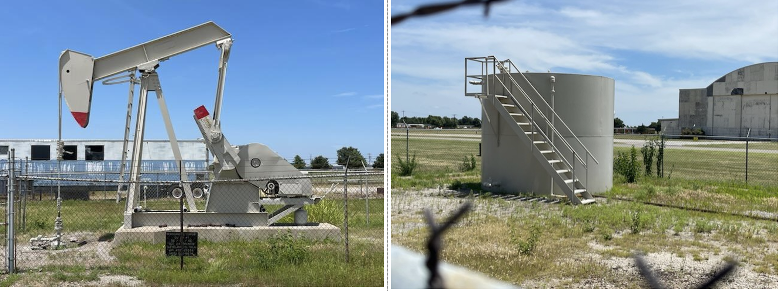
WCTC has a full-scale well facility that plays a crucial role in both teaching and research. Initially functioning as a producing well, this facility has undergone a recent workover operation, transforming it into a specialized resource dedicated to the education of graduate and undergraduate students, as well as to advanced research in the fields of oil and gas, and geothermal well operations. This cutting-edge facility is outfitted with full-scale equipment and state-of-the-art instrumentation, enabling it to offer comprehensive, hands-on training in essential aspects of drilling, completion, and production operations. The practical experience provided here is invaluable for students, bridging the gap between theoretical knowledge and real-world application. Moreover, the University of Oklahoma distinguishes itself as one of the few institutions globally that utilizes such a full-scale well facility for both educational and research purposes. This unique advantage allows the university to remain at the forefront of innovation and excellence in the energy sector, preparing its students with the skills and expertise necessary to lead in this critical field.
Centralizer Testing Facility
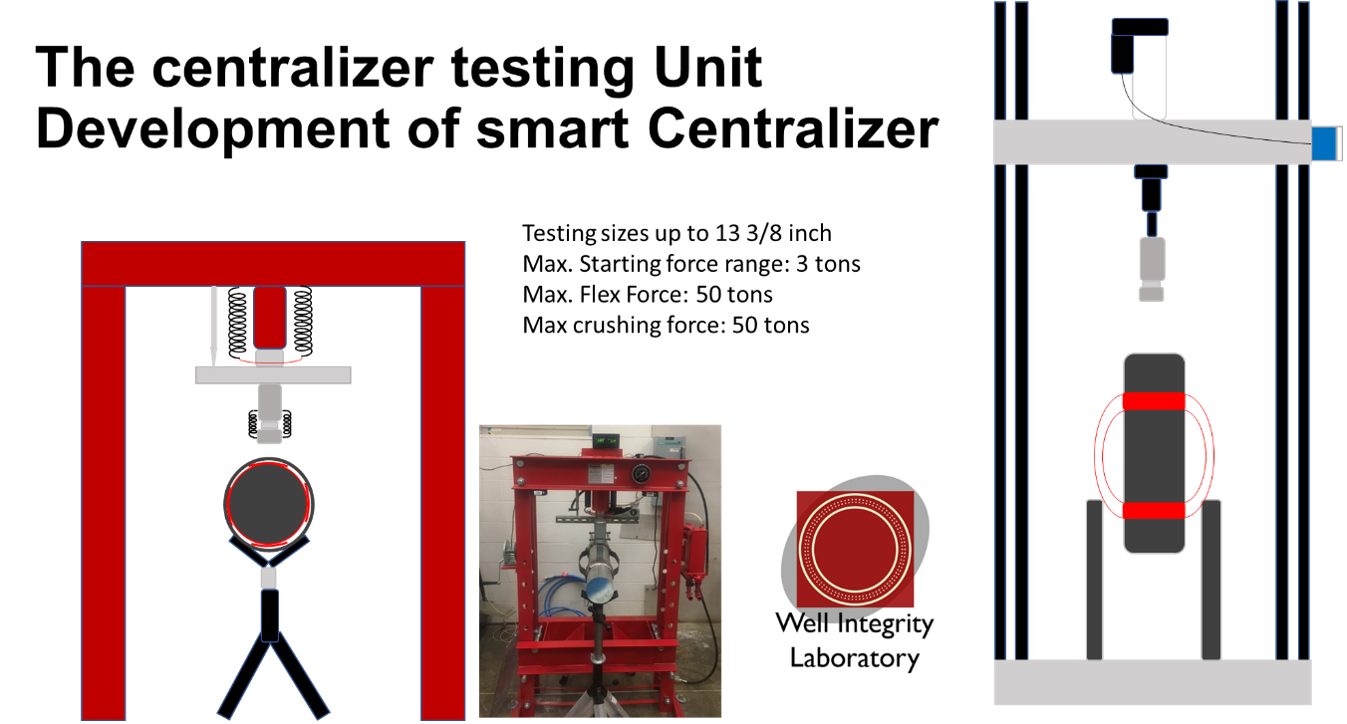
This is a unique setup that allows testing of casing centralizer using API protocol, but also custom defined testing of centralizer combined with machine learning approaches to improve the centralizer application and functionality further.
OCTG Connection Testing Setup
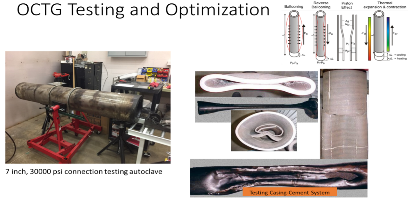
Extreme high-pressure setup allows for connection testing under various wellbore scenarios both under internal and external pressure. The setup is designed for capped end pressure testing or with zero axial loads (fixed ends). It is specifically designed for long-term testing as well as for post-failure investigation of leaking connections.
Large Scale Geothermal Testing setup
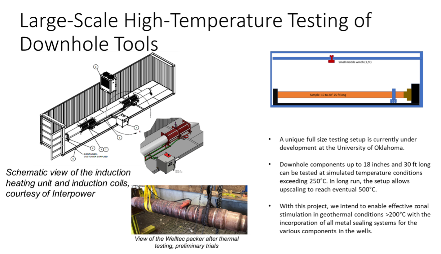
This is a unique, one-of-a-kind, in-the-nation full-scale testing setup designed specifically for geothermal applications. Testing of downhole tools, such as packers, isolation tools, valves, and so on, can be conducted on this full-scale testing setup. The setup is placed in a container that can accommodate a 30ft outer shell pipe/casing in which the equipment under testing can be installed. Currently, the temperature and pressure that the setup can achieve are 350°C (upgradable to 500°C) and 10,000 psi, respectively. Moreover, the setup is equipped with different sensors, data acquisition cards, and software through which the pressure and temperature can be monitored and recorded in real-time. Heating the system is done through the induction coil, while the pressure is provided with the help of pneumatic pumps. With the help of this setup, the pressure in the annulus and packer can be monitored and recorded at a given temperature, and multiple heating cycles can be achieved. The testing time can range from hours to days and weeks, depending on the requirements of the experiment. The setup was built as part of the FORGE-DOE project, and it is available for the geothermal community.

