A step-by-step guide
1. Laying out an initial topology
2. Analyzing your bandwidth needs
3. Taking inventory of your applications
4. Building a test network
5. Making decisions
6. Summary of general design guidelines
As a way of getting started, lay out each of your sites on a map. Because frame relay tariffs are not typically distance sensitive, you can disregard the geographical location in laying out a basic topology. This initial topology will probably be based on your current campus locations and expected host computer placement.
If you will be using multiple frame relay networks, a cost analysis may determine a mixed topology is best-in other words, creating a network of networks, each optimized for the carrier's network. This should minimize costly peer to peer relationships between providers.
If you will use multiple carriers, you may either use your own network to move data between the public networks, or the vendors may offer Network-to-Network Interface (NNI) service directly between themselves. If you accept an NNI agreement, you should understand the size of the NNI links. A single carrier should be assigned lead responsibility for the end-to-end health of your traffic.
You'll need a proper analysis of your bandwidth needs in order to size the network correctly and provide the appropriate expected level of service to your clients. Application performance in the wide area is almost always an order of magnitude lower than on LANs, but you can employ techniques to minimize any negative effects.
Application modeling is itself a mix of science and art. The WAN designer can choose from a variety of modeling approaches. Most assume fairly controlled environments, and may use statistical analysis to project an expected performance specification. Rather than build elaborate models, we prefer to take a more practical, application oriented view, carefully analyzing actual application behavior.
After collecting data on network events generated by applications, design a topology and validate the results of the analysis using a small test network. This approach will quickly isolate problem applications that may need special attention.
You have probably experienced what it's like to be on the wrong end of a modem link, and have suffered through long downloads or slow response time. At low modem speeds, it's easy to recognize the problem: You need more bandwidth on the link. However, as you increase bandwidth, throughput levels off. This is due to delay, or latency, in other parts of the network.
End-to-end latency is the sum of delay in all parts of a networked conversation. It includes router queuing delays, WAN insertion delays, switching delays, propagation delays, even the time required to get hold of the local LAN channel. And that's just the network portion. When a request finally arrives at a remote server it has to be processed and results have to be returned, introducing host-processing delays into the latency equation.
To understand latency and how it relates to frame relay bandwidth parameters, it helps to think of the network not as a pipe, but as a temporary storage area. Information submitted at CIR will be accepted by the network, held by the backbone for a (hopefully short) period of time, and then finally delivered to a remote destination. If you submit more data than your contracted rate-in other words, you submit more data than your Committed Burst rate-you might not get your data out the other side.
Fortunately, when frames are dropped, protocols such as TCP/IP or IPX/SPX will recognize the packet loss, request retransmittal, and begin retransmission of the lost packets. This obviously takes time to detect and recover, which means-you guessed it-more latency.
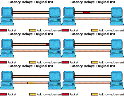
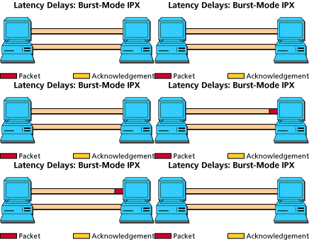
The bad effects of delay are magnified by bad end node protocols. The classic example is with NetWare's original use of the IPX protocol. Each packet sent requires an acknowledgment before the next is sent. In other words, each packet is delayed by the round trip latency time. In contrast, burst mode IPX will allow several packets to be sent before an acknowledgment is received. With proper tuning, end nodes can continually fill the available channel, and the total transaction stream gets delayed only by the one-way latency.

It's theoretically possible to run real-time voice or video across a frame relay link, but you have to make sure that your end-to-end latency isn't too high to degrade quality. For voice, many people can notice delays of under 100 ms, and everybody will notice when it exceeds 300 ms. Even worse, the cloud may have variable delay, or jitter, so that delays occur at many different levels during a single phone conversation.
Equipment vendors that support voice over frame relay can compress voice to consume very little bandwidth-getting it down to 16 Kbps, 8 Kbps, even 4.8 Kbps. Voice may not take much bandwidth, but, remember, that's not the problem, is it? Once again, it's latency.
While you may be able to prioritize voice traffic at a router or FRAD to minimize queuing delay, that won't address delay in the cloud. In these cases, we recommend that you assign priority PVCs through the network and get latency guarantees from your carrier. You'll need to make sure CIR is high, because real-time voice is not bursty traffic, and you'll quickly exceed your BC burst levels.
This table highlights application classes and traffic attributes:
| Interactive | Client-server applications, File-sharing applications, Host terminal | Sensitive to delay | Minimize remote requirements (place resources near client) |
| Store-and-Forward | E-mail delivery, Voicemail exchange, Archiving, Batch jobs, | Delay less important, Can completely consume bandwidth, | Schedule background processes to avoid interfering with delay-sensitive traffic |
| Real Time | Telephony, Videoconferencing | Highly sensitive to delay | Assure quality of service through carrier service-level guarantees and/or dedicated PVCs |
In addition to the applications listed above, there is network overhead to consider: Many protocols, including frame relay itself, introduce extra overhead. In most cases, the overhead is minimal relative to the application payload you're trying to deliver.
While overhead may often be small, there are cases where you'll need to take steps to minimize its impact: For example, low-bandwidth circuits may be consumed by high volumes of IPX Routing Information Protocol (RIP) and Service Advertising Protocol (SAP) traffic. If you have many NetWare servers and use slow links that pass IPX, you will want to minimize this traffic. Fortunately, a number of well-known techniques will help, such as RIP/SAP filters, triggered updates, and link state routing protocols.
Applications may also generate background overhead. For example,
polling by e-mail message transfer agents can be significant.
If you have access to a protocol analyzer, now is the time to crank it up. For each of the applications in your inventory, starting with the most critical applications, capture traffic between end nodes. Get enough samples to simulate actual usage, focusing on the transactions that generate the most volume. Although overall averages are helpful, work to isolate activity that generates the highest traffic. Keep these samples as short as possible.
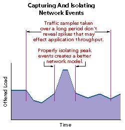
The key item to watch is the amount of traffic in kilobytes offered to the network over the sample period. If it is far beyond a level that the WAN will support (e.g. hundreds of kilobytes per second), you may have to reconsider the application's architecture before you continue.
Collecting data on applications can be a tedious process, but it is imperative. You'll not only need to know the applications, but the likely events that they are to generate. For example, a single mouse click may generate a query returning a megabyte or more of data. Analyzing this information will help you determine alternate application topologies-e.g. replicating data on a nightly basis to eliminate interaction in the wide area, or changing e-mail polling intervals.
After collecting a good set of samples, create a new row in the application spreadsheet for each application event. Plug in the two-way traffic estimates gathered by your analyzer.
You may not be able to complete all columns of the spreadsheet yet, so just fill in what you can. For example, the location of servers may be dependent on your analysis, so you'll have to walk complete this step before you can place them.
Estimate how frequently each of these events is likely to occur. Next, plug in values for an acceptable duration for the event. These values may be dictated by the limits of the application itself, or by a user's expected service level. For example, if users expect all internal e-mail to be delivered within 15 minutes, you'll need to support e-mail polling at a frequency well below that.
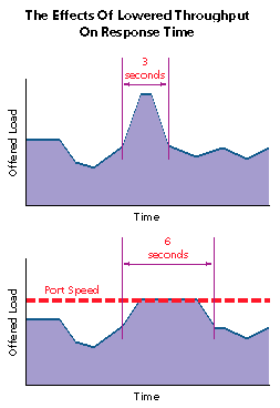
In assigning acceptable duration for an event, you will effectively "flatten" its peak bandwidth requirements. There are limits to how far you can take this: If you delay too long, applications may time out and fail. The exact limits depend on the protocol and applications.
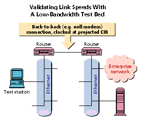
Nothing beats a slow-link test bed. A sample network for testing is the fastest way to determine what application performance will really be like. It's the place to try out new applications before they get deployed. It should be used by application developers and commercial software installation teams.
You can set up a simple test bed using a pair of routers, using a null modem cable between serial ports. Set the clock speed on the serial link to the expected port speed (or maximum burst) rate for the link being simulated.
A word of caution is in order. Your test network will only display the effects of increased latency due to a WAN bandwidth constraint. It won't show propagation and internodal delays that may be rampant in a WAN. It will catch bad applications before they get out, but it won't predict response times.
Now that you understand your applications, you can place them
on the overall topology map. Based on what you've learned, you
may want to move application locations if you can. Before you
start drawing the network, consider each of the applications and
the ways that it might be optimized.
A closer look at our sample application list
In our example network, we can make the following observations:
Draw PVCs between sites as dictated by the application spreadsheet. Don't assign bandwidth numbers just yet. If high priority traffic exists, consider using dedicated PVCs.
Totaling application requirements for a given PVC will give you a worst-case scenario. In most cases, it's highly unlikely that all applications will require maximum bandwidth concurrently. Assess the impact of the occasional collision and delayed response. Statistical modeling tools* are available to help you assess the probability of simultaneous access to the channel.
Create a list of the PVCs determined by the application spreadsheet. Using the output from a modeling tool, or your best judgment, assign the key link parameters-CIR, Bc and port speed to each of your circuits.
If you have multiple PVCs to a given location, it may be possible for the sum of CIR to be higher than the port or access channel rate. This is called oversubscription or overbooking the link. This technique can safely be used in most cases, except when you expect to support real-time traffic such as voice on the link.
Highlight any PVCs containing delay-sensitive traffic for possible priority configuration at the router/FRAD and within the carrier network.
Finally, determine access link rates (56 Kbps or T1) for each of your locations. If you have existing digital facilities in place, you may wish to consolidate them into a single T1 link to reduce cost and provide additional channels for future growth. If you conclude that a location on the frame relay network is already overutilizing 56 Kbps access circuit, consider installing T1 service to avoid installation delays and duplicate cost down the road.
American Hytech Corp.
Azure Technologies
CACI Products Co.
GRC International
Make Systems
MIL 3, Inc.
Network Analysis Center
Network Design And Analysis
Optimal Networks